Liquid Level Control Relay Wiring Diagram
Liquid Level Control System is a system specifically designed to control the level of fluid in tanks. The main aim possessed by these systems is to control the rate with which the pump delivers fluid to the tank and so it can reach the desired level inside the tank.
The purpose of the liquid level system is to maintain a specific level of fluid inside the tank. The liquid level control systems find major applications in industrial processes.
Introduction
In our previous article, we have discussed control systems that are designed with the base that these systems would be able to perform controlled action.
The controller present in the system generates the control signal that is converted into the desired signal by the actuator and is fed to the plant in order to perform the desired action.
The closed-loop operation of the control system allows the feedback signal to get compared with the reference input thereby providing controlled action. This principle of operation is utilized by the liquid level system.
Working of Liquid Level Systems
The crucial components of the water level control system are as follows:
- Fluid tank: Also known as a storage tank, used to hold the desired amount of fluid.
- Measurement system: Senses the level of the fluid inside the tank.
- Controller: The controller is used to maintain the desired level by starting and stopping the pump when gets information by the measurement system.
- Pump: The water from the source is fed to the tank through the pump when actuated by the controller.
The figure below represents the liquid level system:
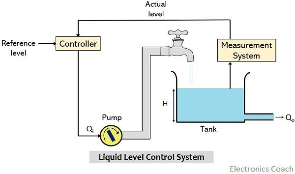
In such systems, fluid from the pump is allowed to enter the tank when the control signal is generated by the controller.
Suppose, the controller actuates the pump and the pump starts filling the tank with an inflow rate of Qi m3/s. Here H denotes the fluid level inside the tank in m and Qo be the outflow rate of the fluid from the tank.
It is clear that to maintain a steady level of the liquid,
Qi = Qo
: H = constant
But there exist some fluctuations in the rate of supply of the fluid.
Basically, these systems are analyzed on the basis of nature of the fluid flowing through the pipes. And this classification is done on the basis of a number called Reynolds number.
- So, if the value of the Reynolds number falls below 2000 then the flow is assumed to be laminar. This means that the fluid, in this case, travels smoothly on a regular path. So, turbulence is not present in this type of flow.
- While if the Reynolds number is more than 3000 to 4000 then, in this case, the flow is not laminar but turbulent.
As we have already discussed in the beginning that these systems possess two main purposes. The first is to maintain the liquid level and the second is the rate of flow of the liquid.
Thus, for the purpose of analysis, the two majorly concerned variables are the level of fluid in the tank and the rate of flow of fluid through the pipes.
So, resistance, capacitance and inertance are regarded as the fundamental parameters of a liquid level control system.
The term inertance corresponds to the inertia forces which comes into action in order to cause acceleration of the fluid through the pipes. It is regarded as an energy-storing element but the amount of stored energy due to inertance is quite small thus is neglected at the time of analysis.
So, the liquid level control system is defined on the basis of only resistance and capacitance associated with the system.
Consider the figure we have shown above. And as we have mentioned that at steady state,
Qi = Qo
However, when the fluid outflows from the tank then there will be some resistance in its flow. The amount of resistance offered depends on the outlet through which the fluid comes out.
In case of a hole as an outlet, the fluid will not flow out easily that causes the generation of resistance. While in the case of the pipe as an outlet, the nature of flow which we have discussed above i.e., laminar or turbulent and the frictional force between liquid and pipe are the deciding factors for the resistance.
Also, the amount of offered resistance increases with the presence of the valve with the pipe at the outlet.
So, generally, the resistance of the liquid level system is expressed as: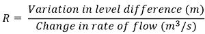
This is defined on the basis of change noticed in the difference in levels of two tanks needed for the unit change in the rate of flow of fluid. This means the ratio depends on the nature of the flow.
Transfer Function of Liquid Level System
Suppose the flow is linearly turbulent where:
- Qo denotes steady-state outflow rate
- qi represents a small change in rate with the fluid is entering from the steady-state value
- q0 shows the small change in the rate with which the fluid is coming out from steady-state
- H is the steady-state level of the fluid inside the tank
- h is the small variation in fluid level from the steady-state value
For liquid level system, the equation of capacitance is given as: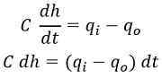
Also,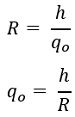
On substituting the value of qo, we will get,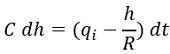
Further,![]()
On transforming![]()
Therefore,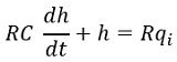
Now, taking Laplace transform, we will get,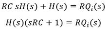
Thus, the transfer function of the system for input qi and output h, we will have,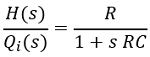
While if qo is considered as the output for input qi, then the Laplace transform of the equation shown above i.e.,
Will be![]()
So, on substituting, H(s) from the transfer function obtained above, we will get,![]()
Therefore,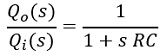
: RC corresponds the time constant i.e., τ, of the liquid level control system.
Posted by: ursuladiscompardaep.blogspot.com
Source: https://electronicscoach.com/liquid-level-control-system.html

Posting Komentar untuk "Liquid Level Control Relay Wiring Diagram"